Copyright Planchard 2012 Alphabet of lines and Precedence of Lines
Copyright Planchard 2012 Alphabet of lines (Cont:) Every line on your drawing has a meaning. In other words, lines are symbols that mean a specific thing. The line type determines if the line is part of the object or conveys information about the object. Lets review the most common line types and widths used in Orthographic projection.
Copyright Planchard 2012 Alphabet of lines and Precedence of Lines Stephen H. Simmons TDR 200
Line types and conventions for mechanical drawings are covered in ANSI Standard Y14.2M. There are four distinct thicknesses of lines: Very Thick, Thick, Medium and Thin..
In other words, lines are symbols that mean a specific thing. The line type determines if the line is part of the object or conveys information about the object. Lets review the most common line types and widths used in Orthographic projection..
Since visible lines are the most important lines, they must stand out from all other secondary lines on the drawing..
They represent the hidden features of an object. Hidden lines should always begin and end with a dash, except when a dash would form a continuation of a visible line..
If possible, dimension lines are aligned and grouped for uniform appearance. All dimension lines terminate with an arrowhead on mechanical engineering drawings; a slash, or a dot in architecture. The preferred ending is the arrowhead. Note: In SolidWorks, inserted dimensions in the drawing are displayed in gray. Imported dimensions from the part are displayed in black..
An extension line must not touch the feature from which it extends, but should start approximately (2 - 3 mm) from the feature being dimensioned and extended the same amount beyond the arrow side of the last dimension line..
When extension lines cross dimension lines close to an arrowhead, breaking the extension line is recommended for clarity..
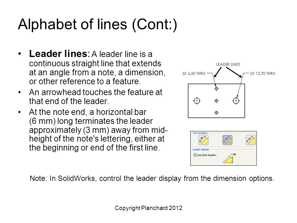
An arrowhead touches the feature at that end of the leader. At the note end, a horizontal bar (6 mm) long terminates the leader approximately (3 mm) away from mid- height of the note s lettering, either at the beginning or end of the first line. Note: In SolidWorks, control the leader display from the dimension options..
Unless unavoidable, leaders should not be bent in any way except to form the horizontal terminating bar at the note end of the leader..
Leaders or extension lines may cross an outline of a part or extension lines if necessary, but they usually remain continuous and unbroken at the point of intersection. When a leader is directed to a circle or a circular arc, its direction should be radial..
Line weight is thick (0.5 – 0.6 mm)..
Centerlines are used to represent the axes of symmetrical parts of features, bolt circles, paths of motion, and pitch circles. Every circle, and some arcs, should have two centerlines that intersect at their center of the short dashes..
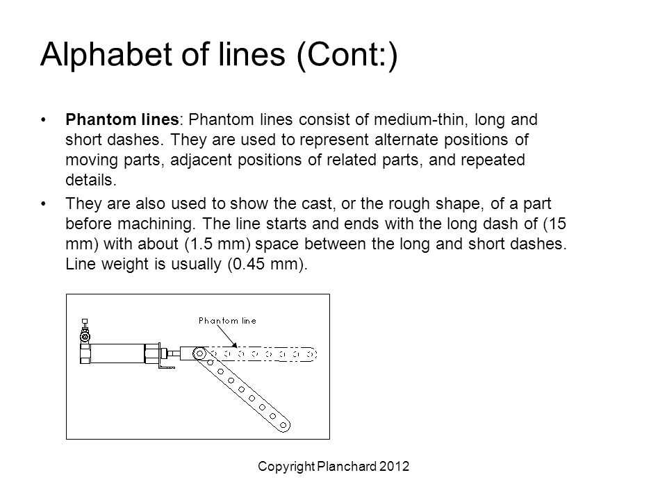
They are used to represent alternate positions of moving parts, adjacent positions of related parts, and repeated details. They are also used to show the cast, or the rough shape, of a part before machining. The line starts and ends with the long dash of (15 mm) with about (1.5 mm) space between the long and short dashes. Line weight is usually (0.45 mm)..
Spacing should be approximately (3 mm) and at an angle of 45°. The section pattern is determined by the material being cut or sectioned. Section lines are commonly referred to as cross-hatching. .
Line type is phantom. Arrows are located at the ends of the cutting plane line and the direction indicates the line of sight into the object..
Since the visible features of a part (object lines) are represented by thick solid lines, they take precedence over all other lines. If a centerline and cutting plane coincides, the more important one should take precedence. Normally the cutting plane line, drawn with a thicker weight, will take precedence. The following list gives the preferred precedence of lines on your drawing:.
Visible / Feature (object) Lines 2. Hidden (dashed) Lines 3. Cutting plane Lines 4. Centerlines.
Break Line 6. Dimension 7. Extension Lines / Leader Lines 8. Section Lines / Crosshatch Lines.

vocab.txt · intfloat/e5-large at 724bada59cdfb103b9e26342d8ca661fb103b07c

Alphabet of lines and Precedence of lines Flashcards
Copyright Planchard 2012 Alphabet of lines and Precedence of Lines
Copyright Planchard 2012 Alphabet of lines and Precedence of Lines
Copyright Planchard 2012 Alphabet of lines and Precedence of Lines Stephen H. Simmons TDR ppt download

Draw Shapes with Perpendicular Lines: drawspace module 2.1.A11 by Brenda Hoddinott
BNG 101 – Engineering Graphics Slide Set 1 – Alphabet of Lines

Pan-Rational and Irrational Rhythm

Alphabet Lines Cover Lines Labeling Symbols Stock Vector (Royalty Free) 1397156063
Coherent/mwc/romana/relic/a/usr/dict/common at master · gspu/Coherent · GitHub

Technical Drafting - Alphabet of Lines I GV Envisions Lecture

ArtStation - Plate No. 12 - Alphabet of Lines Application

Mrs Speechie P - Prewriting lines and shapes by age! These