Jig & Fixture Design Dr.Apiwat Muttamara. - ppt download
Workholder (Jig & fixture) Introduction Modern Manufacturing FMS, CIM Workholder (Jig & fixture)
Jig & Fixture Design Dr.Apiwat Muttamara
Introduction. Modern Manufacturing. FMS, CIM. Workholder (Jig & fixture)
Basic Principle of workholder. Identify the types of locators and support used fro jigs and fixtures.
Purpose of tool design. To improve efficiency and productivity. To reduce cost.
Often the terms jig and fixture are confused or used interchangeably; however, there are clear distinctions between these two tools. Although many people have their own definitions for a jig or fixture, there is one universal distinction between the two. Both jigs and fixtures hold, support, and locate the workpiece.. The differentiation between these types of workholders is in their relation to the cutting tool. As shown in Figure 1-1, jigs use drill bushings to support and guide the tool. Fixtures, Figure 1-2, use set blocks and thickness, or feeler, gages to locate the tool relative to the workpiece. references the cutting tool.
The most-common jigs are drill and boring jigs. These tools are fundamentally the same. The difference lies in the size, type, and placement of the drill bushings. Boring jigs usually have larger bushings. These bushings may also have internal oil grooves to keep the boring bar lubricated. Often, boring jigs use more than one bushing to support the boring bar throughout the machining cycle. In the shop, drill jigs are the most-widely used form of jig. Drill jigs are used for drilling, tapping, reaming, chamfering, counterboring, countersinking, and similar operations. Occasionally, drill jigs are used to perform assembly work also. In these situations, the bushings guide pins, dowels, or other assembly elements. Jigs are further identified by their basic construction. The two common forms of jigs are open and closed. Open jigs carry out operations on only one, or sometimes two, sides of a workpiece. Closed jigs, on the other hand, operate on two or more sides. The most-common open jigs are template jigs, plate jigs, table jigs, sandwich jigs, and angle plate jigs. Typical examples of closed jigs include box jigs, channel jigs, and leaf jigs. Other forms of jigs rely more on the application of the tool than on their construction for their identity. These include indexing jigs, trunnion jigs, and multi-station jigs. Specialized industry applications have led to the development of specialized drill jigs. For example, the need to drill precisely located rivet holes in aircraft fuselages and wings led to the design of large jigs, with bushings and liners installed, contoured to the surface of the aircraft. A portable air-feed drill with a bushing attached to its nose is inserted through the liner in the jig and drilling is accomplished in each location. Fixtures.
have a much-wider scope of application than jigs. These workholders are designed for applications where the cutting tools cannot be guided as easily as a drill. With fixtures, an edge finder, center finder, or gage blocks position the cutter. Examples of the more-common fixtures include milling fixtures, lathe fixtures, sawing fixtures, and grinding fixtures. Moreover, a fixture can be used in almost any operation that requires a precise relationship in the position of a tool to a workpiece. Fixtures are most often identified by the machine tool where they are used. Examples include mill fixtures or lathe fixtures. But the function of the fixture can also identify a fixture type. So can the basic construction of the tool. Thus, although a tool can be called simply a mill fixture, it could also be further defined as a straddle-milling, plate-type mill fixture. Moreover, a lathe fixture could also be defined as a radius-turning, angle-plate lathe fixture. The tool designer usually decides the specific identification of these tools.
Workholders for high-volume production are usually permanent tools. These permanent jigs and fixtures are most often intended for a single operation on one particular part. The increased complexity of permanent workholders yields benefits in improved productivity and reduced operator decision-making, which result in the tool having a lower average cost per unit or per run. Therefore, more time and money can be justified for these workholders. In the case of hydraulic or pneumatic fixtures, inherent design advantages can dramatically improve productivity and, hence, reduce per-unit costs even further, even though the initial cost to construct these fixtures is the most expensive of all fixture alternatives. In some cases, where machine-loading considerations are paramount, such as a pallet-changing machining center, even duplicate permanent fixtures may be justified. Permanent jigs and fixtures are typically constructed from standard tooling components and custom-made parts. Figure 1-3 shows a typical permanent workholder for a drilling operation.
Modular fixtures achieve many of the advantages of a permanent tool using only a temporary setup. Depicted in Figure 1-4, these workholders combine ideas and elements of permanent and general-purpose workholding.
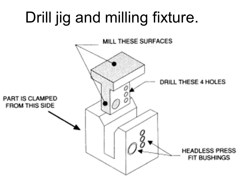
The performance of any workholder is critical to the complete usefulness of the tool. If the workholder cannot perform the functions desired in the manner intended, it is completely useless, regardless of the cost or the extent of the detail. As the performance of a permanent, modular, or general-purpose workholder is considered, several factors about the machine tools must be known. These factors include the type, size, and number of machine tools needed for the intended operations. Workholders are sometimes designed to serve multiple functions. For example, it is possible to have a workholder that acts both as a drill jig and a milling fixture. These tools are called combination tools or multiple-function workholders. Figure 1-6 shows a typical temporary workholder for drilling and milling operations on the same part. In this example, since the workholder has provisions for both milling and drilling, it is classified as both a.
Assembly • Welding fixtures Inspection • Mechanical-inspection fixtures • Optical-inspection fixtures • Electronic-inspection fixtures. NON-MACHINING APPLICATIONS: Assembly • Welding fixtures • Mechanical-assembly fixtures (Riveting, stapling, stitching, pinning, etc.) • Soldering fixtures Inspection • Mechanical-inspection fixtures • Optical-inspection fixtures • Electronic-inspection fixtures Finishing • Painting fixtures • Plating fixtures • Polishing fixtures • Lapping fixtures • Honing fixtures Miscellaneous • Layout templates • Testing fixtures • Heat-treating fixtures.
Purpose and function of work holders. Consistently position workpiece relative to the tool. Hold workpiece in position against tool forces. Restrict deflection of the workpiece due to tool and holding forces.
A clamp is a moveable part of a fixture, the purpose of which is to provide a holding force. A support is a fixed or moveable part of a fixture, the purpose of which is to prevent workpiece deflection under the action of imposed cutting forces or clamping forces.
We have two objectives when mounting a part in a fixture for machining: 1. Accurately position the part at the desired coordinates. 2. Restrict all six degrees of freedom so that the part cannot move. A widely used method of accomplishing these two objectives uses the principle, so-called because it entails three steps that employ three, then two, then one fixed points of known location. Since that adds up to six fixed points, it’s also known as the six point method. In the three steps of the method, three mutually perpendicular planes, called datum planes, are introduced, one at each step. These three planes define the workpiece position, and together with opposing clamping forces fully constrain the part. Let’s take a look at the details of the method. Translational Rotational.
First Plane Geometry tells us that three points are required to define a plane. This is the 3 in So, three specific points are used to define the first plane. Fewer than three points cannot define a plane, and in the real world dimensional tolerances mean that four or more points will not be coplanar. A real-world, less than ideally perfect part placed on four or more reference points will, in fact, rest on only three of the points due to its less than perfect surface. Different parts may rest on different combinations of three points, resulting in variation between finished parts. A stool can be used to illustrate this concept. A two-legged stool would certainly be unstable. A three-legged stool sits rock-solid. A four-legged stool is often found to rock. In the illustration, a three dimensional part, represented by a cube, is placed on a datum plane defined by three support points. The part’s six degrees of freedom have.
TIPS • Use the largest surface of the part for the first ( primary ) reference plane. • Position the three support points as far apart as possible. • If more than three support points are required to prevent deflection, make the additional points adjustable.
Try to choose the second largest surface of the part for the two support points of the second plane. • If more than two support points are required to prevent deflection, make the additional points adjustable.
Machined is Best It’s best if the workpiece surfaces intended to contact the support points are machined. Cast surfaces are usable, but then tend to create tolerance problems. Machined holes are the number one choice. Two machined holes can be used to eliminate all but one degree of freedom. Repeatability Repeatability is a paramount concern. It means that each part should be nearly identical to each other part coming off the same fixture. Nearly identical actually has a specific, quantifiable meaning: key dimensions of all parts produced on the same fixture must fall within defined tolerances. In order to stay within tolerances, it’s best if the workpiece surfaces intended to contact the support points are machined. Cast surfaces are usable, but they tend to create tolerance problems. Machined holes are the number one choice, because two machined holes can be used to eliminate all but one degree of freedom. The next best feature to use for consistent locating is machined surfaces at right angles. The machined surface desired here can simply be a tab or small flat specifically included for locating purposes. Repeatability is achieved through application of the method to the three aspects of the locating process: 1. Supporting 2. Locating (positioning) 3. Holding Supporting • The part is supported from below with reference to the Z axis. (Introduction of the first reference plane.) • Gravity positions the part against the support locator. • Provide adjustable auxiliary support points as needed to prevent deflection. • Vertical location with respect to the fixture is now established. Locating The part is positioned horizontally, in the X-Y plane. (Introduction of the second and third reference planes.) Holding • The part is clamped against fixed locators. Therefore, a known and unvarying position of the part is maintained with respect to the X, Y, and Z axes. • One strap clamp or clamp arm will restrict the workpiece in three dimensions due to friction between the workpiece and clamp. However, friction alone may not be enough to prevent the workpiece from moving during machining. • Cutting forces will not move a properly supported and clamped part. Locating • The part is positioned horizontally, in the X-Y plane. (Introduction of the second and third reference planes).
To perform properly, workholders must accurately and consistently position the workpiece relative to the cutting tool, part after part. To accomplish this, the locators must ensure that the workpiece is properly referenced and the process is repeatable.
Workpiece should automatically come to rest against locators despite operators skill or effort. Location system must consistently position all workpieces in relations to the tool despite the variations in the working environment. e.g. surface irregularities, wear of locators, dirt, temperatures difference. Referencing is a dual process of positioning the workpiece relative to the workholder, and the workholder relative to the cutting tool. Referencing the workholder to the cutting tool is performed by the guiding or setting devices. With drill jigs, referencing is accomplished using drill bushings. With fixtures, referencing is accomplished using fixture keys, feeler gages, and/or probes. Referencing the workpiece to the workholder, on the other hand, is done with locators. If a part is incorrectly placed in a workholder, proper location of the workpiece is not achieved and the part will be machined incorrectly. Likewise, if a cutter is improperly positioned relative to the fixture, the machined detail is also improperly located. So, in the design of a workholder, referencing of both the workpiece and the cutter must be considered and simultaneously maintained. Repeatability is the ability of the workholder to consistently produce parts within tolerance limits, and is directly related to the referencing capability of the tool. The location of the workpiece relative to the tool and of the tool to the cutter must be consistent. If the jig or fixture is to maintain desired repeatability, the workholder must be designed to accommodate the workpiece s locating surfaces. The ideal locating point on a workpiece is a machined surface. Machined surfaces permit location from a consistent reference point. Cast, forged, sheared, or sawed surfaces can vary greatly from part to part, and will affect the accuracy of the location.
Surface should be machined to insure accurate location. Choose locating point as far as possible.
When holding force cannot be applied more than six locators can be used. Less operator skill is required when placing the workpiece in the holder. To Increase center line control.
Place locators far for more stability and to minimize the effect of wear of locators and workpiece irregularity. Top heavy workpiece may led to stability. Poorly placed holding force. Not enough locators.
Where possible, tool-forces should be such that they force the workpiece into contact with the locators. Holding forces should not be in the opposite direction to the tool forces.
Achieved by foolproofing pin.
1. Make locators easy to clean 2. Make them self cleaning 3. Protect them.
The final consideration in the placement of locators involves the problem of chip control. Chips are an inevitable part of any machining operation and must be controlled so they do not interfere with locating the workpiece in the workholder. Several methods help minimize the chip problem. First, position the locators away from areas with a high concentration of chips. If this is not practical, then relieve the locators to reduce the effect of chips on the location. In either case, to minimize the negative effects of chips, use locators that are easy to clean, self-cleaning, or protected from the chips. Figure 3-14 shows several ways that locators can be relieved to reduce chip problems. Coolant build-up can also cause problems. Solve this problem by drilling holes, or milling slots, in areas of the workholder where the coolant is most likely to build up. With some workholders, coolant-drain areas can also act as a removal point for accumulated chips. When designing a workholder, always try to minimize the chip problem by removing areas of the tool where chips can build up. Omit areas such as inside corners, unrelieved pins, or similar features from the design. Chip control must be addressed in the design of any jig or fixture.
Sharp locators Burr and Chip Relief
Clamping Rules of Thumb • Define three reference planes on the workpiece and fixture. • Provide one opposing clamping force opposite each plane to restrict movement. • When in doubt, rely on additional cylinders to take up uncertainty.
. Types of workpiece location
There are three general forms of location: plane, concentric, and radial. Plane locators locate a workpiece from any surface. The surface may be flat, curved, or have an irregular contour. In most applications, plane-locating devices locate a part by its external surfaces, Figure 3-2a. Concentric locators, for the most part, locate a workpiece from a central axis. This axis may or may not be in the center of the workpiece. The most-common type of concentric location is a locating pin placed in a hole. Some workpieces, however, might have a cylindrical projection that requires a locating hole in the fixture, as shown in Figure 3-2b. The third type of location is radial. Radial locators restrict the movement of a workpiece around a concentric locator, Figure 3-2c. In many cases, locating is performed by a combination of the three locational methods.
Radial location Supplement to the concentric locators to provide a specified fixed relationship to the concentric locator.
Combined location Most workholders use a combination of locational methods to completely locate a workpiece.
1. External locators. Devices used to locate the part from external surface. Two basic forms of external locators are fixed or adjustable.
Flat surfaces are common workpiece features used for location. Locating from a flat surface is a form of plane location. Supports are the principal devices used for this location. The three major forms of supports are solid, adjustable, and equalizing, Figure 3-3.
easily available in market, Pin locators are available in two styles: plain and shouldered. Ends are round, flat or bullet. Made and (0.013 and 0.05 mm) undersize to prevent jamming and binding. Improve installation; installed ends are smaller than location ends by (1.588 mm) Press fit are installed in the tool body. Slip fit pins are used with liner busing which is installed in the tool body.
Adjustable support Threaded type adjustable supports
Spring type adjustable support with locking nut
Fixed locators – machined to suit specific size when the size variations are not large – example: base plate. Compensating locators: conical and self adjusting.
Disadvantage – extra time for machining and no replacement for wear or damaged locators.
Assembled locators Similar to integral locators Replaceable locators
Cylinder can come along upward Y (1), forward X(1) , Backward Z(1) and rotation along Z ( 2) – 5 movement is possible.
Geometric & Dimension Control
Only degree of freedom is upward movement. Often difficult to lift the workpiece – ejecting device can be used. Chips and burs can lock the nest. Partial. FULL.
Advantage: Cost is reduced as the location is not critical.
Used for small and compact parts.
15. Spring stop buttons Work same like spring pin but are designed for large workpiece.
One method to help ensure accurate location is the installation of spring-loaded buttons or pins in the workholder, Figure These devices are positioned so their spring force pushes the workpiece against the fixed locators until the workpiece is clamped. These spring-loaded accessories not only ensure repeatable locating but also make clamping the workpiece easier.
Trick of DESIGN. Avoiding Redundant Location. Another condition to avoid in workholder design is redundant, or duplicate, location. Redundant locators restrict the same degree of freedom more than once. The workpieces in Figure 3-15 show several examples. The part at (a) shows how a flat surface can be redundantly located. The part should be located on only one, not both, side surfaces. Since the sizes of parts can vary, within their tolerances, the likelihood of all parts resting simultaneously on both surfaces is remote. The example at (b) points out the same problem with concentric diameters. Either diameter can locate the part, but not both. The example at (c) shows the difficulty with combining hole and surface location. Either locational method, locating from the holes or locating from the edges, works well if used alone. When the methods are used together, however, they cause a duplicate condition. The condition may result in parts that cannot be loaded or unloaded as intended.
Foolproofing prevents improper loading of a workpiece. The problem is most prevalent with parts that are symmetrical or located concentrically. The simplest way to foolproof a workholder is to position one or two pins in a location that ensures correct orientation, Figure With some workpieces, however, more-creative approaches to foolproofing must be taken.
Figure 3-18 shows ways to foolproof part location. In the first example, shown at (a), an otherwise-nonfunctional foolproofing pin ensures proper orientation. This pin would interfere with one of the tabs if the part were loaded any other way. In the next example, shown at (b), a cavity in the workpiece prevents the part from being loaded upside-down. Here, a block that is slightly smaller than the opening of the part cavity is added to the workholder. A properly loaded part fits over the block, but the block keeps an improperly loaded part from entering the workholder.
The workpiece itself determines the overall size of a locating element. The principle rule to determine the size of the workpiece locator is that the locators must be made to suit the MMC (Maximum-Material Condition) of the area to be located. The MMC of a feature is the size of the feature where is has the maximum amount of material. With external features, like shafts, the MMC is the largest size within the limits. With internal features, like holes, it is the smallest size within the limits. Figure 3-20 illustrates the MMC sizes for both external and internal features.
Sizing cylindrical locators is relatively simple. The main considerations are the size of the area to be located and the required clearance between the locator and the workpiece. As shown in Figure 3-21, the only consideration is to make the locating pin slightly smaller than the hole. In this example, the hole is specified as in diameter. Following the rule of MMC, the locator must fit the hole at its MMC of Allowing for a clearance between the pin and the hole, desired pin diameter is calculated at Standard locating pins are readily available for several different hole tolerances, or ground to a specific dimension. A standard 1/2 Round Pin with head diameter would be a good choice.
Locating the workpiece is the first basic function of a jig or fixture. Once located, the workpiece must also be held to prevent movement during the operational cycle. The process of holding the position of the workpiece in the jig or fixture is called clamping. The primary devices used for holding a workpiece are clamps. To perform properly, both the clamping devices and their location on the workholder must be carefully selected. Factors in Selecting Clamps. Clamps serve two primary functions. First, they must hold the workpiece against its locators. Second, the clamps must prevent movement of the workpiece. The locators, not the clamps, should resist the primary cutting forces generated by the operation. Holding the Workpiece Against Locators. Clamps are not intended to resist the primary cutting forces. The only purpose of clamps is to maintain the position of the workpiece against the locators and resist the secondary cutting forces. The secondary cutting forces are those generated as the cutter leaves the workpiece. In drilling, for example, the primary cutting forces are usually directed down and radially about the axis of the drill. The secondary forces are the forces that tend to lift the part as the drill breaks through the opposite side of the part. So, the clamps selected for an application need only be strong enough to hold the workpiece against the locators and resist the secondary cutting forces. The relationship between the locators and clamps can be illustrated with a milling-machine vise. In Figure 3-22, the vise contains both locating and clamping elements. The solid jaw and vise body are the locators. The movable jaw is the clamp. The vise is normally positioned so that the locators resist the cutting forces. Directing the cutting forces into the solid jaw and vise body ensures the accuracy of the machining operation and prevents workpiece movement. In all workholders, it is important to direct the cutting forces into the locators. The movable vise jaw, like other clamps, simply holds the position of the workpiece against the locators. Holding Securely Under Vibration, Loading, and Stress. The next factors in selecting a clamp are the vibration and stress expected in the operation. Cam clamps, for example, although good for some operations, are not the best choice when excessive vibration can loosen them. It is also a good idea to add a safety margin to the estimated forces acting on a clamp. Preventing Damage to the Workpiece. The clamp chosen must also be one that does not damage the workpiece. Damage occurs in many ways. The main concerns are part distortion and marring. Too much clamping force can warp or bend the workpiece. Surface damage is often caused by clamps with hardened or non-rotating contact surfaces. Use clamps with rotating contact pads or with softer contact material to reduce this problem. The best clamp for an application is one that can adequately hold the workpiece without surface damage. Improving Load/Unload Speed. The speed of the clamps is also important to the workholder s efficiency. A clamp with a slow clamping action, such as a screw clamp, sometimes eliminates any profit potential of the workholder. The speed of clamping and unclamping is usually the most-important factor in keeping loading/unloading time to a minimum.
Simple clamps should be used. Quick loading and unloading should be permitted. Production rate should be considered. 2.Cutting pressures. Understanding of cutting forces may eliminate need to restrain 12 DOF. Drilling – Torque and upwards force. Milling operation horizontal force should be directed towards jaw. 3.Part damage. Excessive clamping leads to elastic deformation. 4.Clamping and location. Tool forces tend to move the workpiece away from the locators.
B. CAM. A. Screw. D. Toggle Linkage. C. Wedge. E. Lever. F. Combined screw and wedge.
Basic types of clamps 1.Strap clamp
When fixturing an automated machine, check the complete tool path before using the workholder. Check both the machining cycle and return cycle of the machine for interference between the cutters and the clamps. Occasionally programmers forget to consider the tool path on the return cycle. One way to reduce the chance of a collision and eliminate the need to program the return path is simply to raise the cutter above the highest area of the workpiece or workholder at the end of the machining cycle before returning to the home position. Most clamps are positioned on or near the top surface of the workpiece. The overall height of the clamp, with respect to the workpiece, must be kept to a minimum. This can be done with gooseneck-type clamps, Figure As shown, the gooseneck clamp has a lower profile and should be used where reduced clamp height is needed.
2.Screw clamp Direct Pressure screw clamps
Indirect Pressure (Magnification is possible by using leverage
Direct – tendency to loosen during machining.
Indirect – efficient and safest
Move completely clear of the workpiece. High ratio of holding force to actuation force. Limited range of movement. Inability to compensate for different thickness (suitable to only slight changes of workpiece thickness)
A possible tightening with a single turn is as efficient as screwing 10 turns, but so much faster
Jigs are work holders, which are designed to hold, locate, and support a workpiece while guiding the cutting tool throughout its cutting cycle. Drill jigs are – drilling, tapping, reaming, countersinking, counter boring, chamfering, and spot facing. B. Design considerations. 1. General, machine and process. General Consideration. Justification of manufacturing cost reduction. Machine Consideration. 1. Size, Type, and Capabilities of machine. 2. Machine should be capable of handling the part – shape, size and accuracy. 3. Enough space to mount Workholding device. 4. Tool designer must know about – table size, T slot size, machine travel axis.
2. If the part is not pre-processed first-operating jigs are used to make hole to serve for location purpose is subsequent steps. 3. Multiple jigs and fixtures can be used for one part. 4. Chip removal should be considered for each manufacturing step.
2. Plate containing hole or bushings to guide a drill. 3. Place on parts.
b. Plate Template jig equipped with clamping device.
Universal jigs utilize a handle connected to a cam or rack and pinion to move either a busing plate or nest plate. Parts held in the universal jigs have surface adaptable to fitting against the surfaces of the bushing plate and nest. Changing bushings it can be used for different components.
Reduces number of setups but increase in design and manufacturing cost of jigs.
tumble box Tumble jigs permit machining form all six sides.
4. C-Washer. 5. Drill bushing. 6. Index pin. 7. Spring. 8. Bushing plate. Used to drill hoes located in pattern. Location for the holes is generally taken from the first hole drilled.
H = Angular Depth = x P. H/8 = Shortening of major dia = x P. H/4 = Shortening of minor dia = x P. d = Actual Depth = x P. r = Radius at the Root = x P. Hn = Basic height of Internal Thread = x P. Hs = Basic height of External Thread = x P.
Jig & Fixture Design Dr. Apiwat Muttamara. Magnetic chuck. - ppt

10 Geometric Tol ideas geometric, geometric tolerancing
Week 2:- BiW Fixture Basics Challenge

PPT - Dr.Apiwat Muttamara PowerPoint Presentation, free download

Jigs and Fixtures, PDF, Drill

Jig & Fixture Design Dr.Apiwat Muttamara. - ppt download

JIG and Fixture Design Services at best price in Pune

PDF) Jig and fixture

PPT - Dr.Apiwat Muttamara PowerPoint Presentation, free download

Jigs and fixtures imp